Adafruit32x16RGB
I am working on a project using 16x32 RGB Panel.
Here is a video of the panel working:
I wanted to figure out the timing for the interface so I wrote the code myself without using the sample code.
Here is the sample code:
// test the 32x16 LED board.  Public Domain.

#define A     A0
#define B     A1
#define C     A2
#define LAT   A3
#define OE    9
#define CLK   8
#define R1    2
#define G1    3
#define B1    4
#define R2    5
#define G2    6
#define B2    7

void setup() {
  Serial.begin(115200);

  pinMode(R1,OUTPUT);
  pinMode(G1,OUTPUT);
  pinMode(B1,OUTPUT);
  pinMode(R2,OUTPUT);
  pinMode(G2,OUTPUT);
  pinMode(B2,OUTPUT);
  pinMode(CLK,OUTPUT);
  pinMode(OE,OUTPUT);
  pinMode(A,OUTPUT);
  pinMode(B,OUTPUT);
  pinMode(C,OUTPUT);
  pinMode(LAT,OUTPUT);

  digitalWrite(A,LOW);
  digitalWrite(B,LOW);
  digitalWrite(C,LOW);
  digitalWrite(LAT,LOW);
  digitalWrite(OE,LOW);
  digitalWrite(CLK,HIGH);
}

void updateRow(int i) {
    digitalWrite(OE,LOW);

    // Set the row address
    if ( i & 0x1 ) {
      digitalWrite(A,HIGH);
    } else {
      digitalWrite(A,LOW);
    }
    if ( i & 0x2 ) {
      digitalWrite(B,HIGH);
    } else {
      digitalWrite(B,LOW);
    }
    if ( i & 0x4 ) {
      digitalWrite(C,HIGH);
    } else {
      digitalWrite(C,LOW);
    }

    for ( uint8_t x = 0; x < 64; x++ ) {
      digitalWrite(CLK,LOW);

      if ( x > 31 ) {
        // This will end up on the display closest to the arduino
        digitalWrite(R1,HIGH);
        digitalWrite(G1,HIGH);
        digitalWrite(B1,HIGH);
        digitalWrite(R2,LOW);
        digitalWrite(G2,LOW);
        digitalWrite(B2,HIGH);
      } else {
        // This will end up on the display farthest from the arduino
        digitalWrite(R1,LOW);
        digitalWrite(G1,HIGH);
        digitalWrite(B1,LOW);
        digitalWrite(R2,HIGH);
        digitalWrite(G2,LOW);
        digitalWrite(B2,LOW);
      }

      digitalWrite(CLK,HIGH);
    }
    digitalWrite(LAT,HIGH);
    digitalWrite(LAT,LOW);
    digitalWrite(OE,HIGH);
}

void loop() {

  for ( int i = 0; i < 8; i++ ) {
    updateRow(i);
  }
}
Here is a video of it working:
I tried the sample programs with 2 cascaded displays and they were mirrored for some reason. I'm not sure why. Also, the first row is corrupted. Here are videos of that happening:
I have started working on refreshing the display using a Xula-50 FPGA board. Here is the Timing Diagram I am using in the FPGA code. More videos and Verilog code will be coming soon.
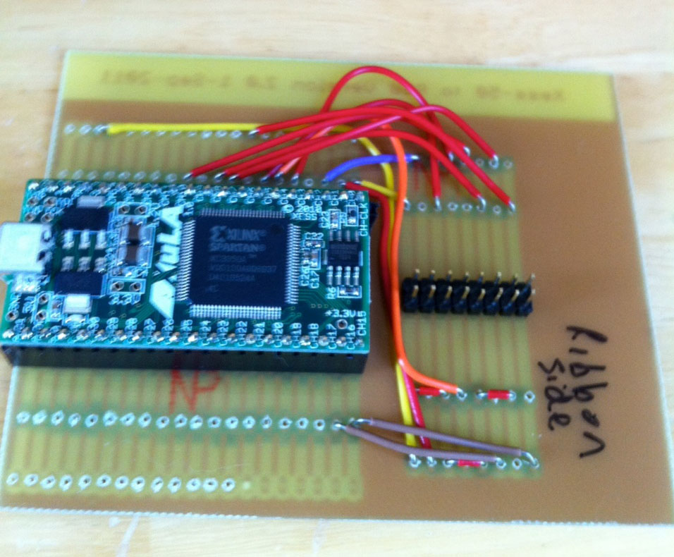
Here is the circuit board I created to interface the RGB panel with the Xula-50: 
(yes there are 7 holes I didn't drill because my 2nd drill bit broke so I gave up! Fortunately, I didn't need them for this.)
Here are two panels that are controlled by the xula-50 board: